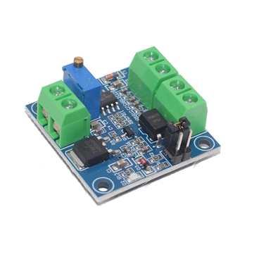

1. Description:
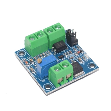
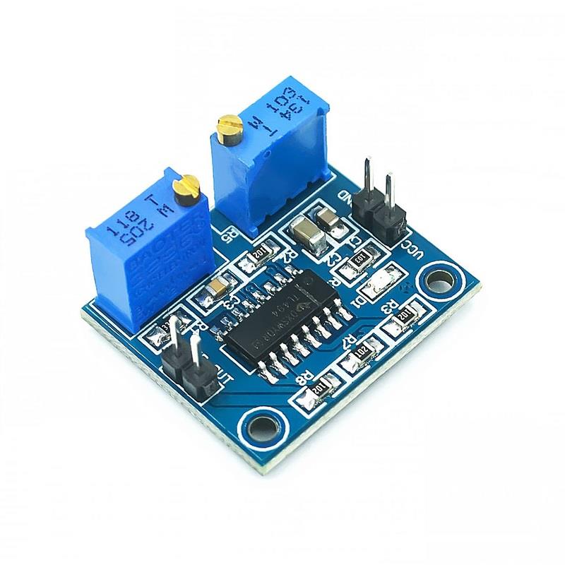
The PWM transfer voltage module LC-LM358-PWM2V converts the PWM digital signals into 0 to 10V analog signals.
It can be used as signal interface switching for PLC or other
industrial control boards. The output voltage is regulated by adjusting
the duty ratio of the PWM. The modules are small in size and easy to use
in different places.
2. Features:
1. MCU embedded technology
2. Easy to operate, fine tuned by potentiometer
3. Select the PWM signal input level range through short-circuit
4. The module is smaller, easy to carry and use
3. Parameter:
1. Work Voltage:DC 12V-30V; (> 100MA)
2. PWM Receiver Frequency:1KHZ-3KHZ
3. PWM signal input level range:
The peak of 4.5V to 10V level. The short cap install in ‘5V’. This level is used for normal controller or 5V MCU
The peak of 12V to 24V level, so inserted in 24V. The short cap install in ‘24V’. This level is used for normal PLC controller
4. Conversion range:0%-100% PWM to 0-10V
5. Allowable error:5%

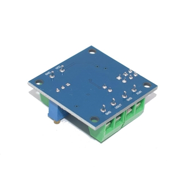
4. Hardware Interface:
VCC | DC 12V-30V |
GND | Ground |
PWM | Positive of PWM input signal |
GND | Negative of input signal |
VOUT | Output Voltage 0-10V |
GND | Output Voltage Ground |
5. Operation instructions:
After power on, without input signal, the output is 0V, so only input can output.
The first time when the power is on, it is best to do a calibration
debugging:Input a 50% duty ratio signal to PWM/GND and adjust the
relative amplitude short cap.
The frequency is 1KHZ-3KHZ, Measured VOUT
and GND with a multimeter and it will display 5V. Adjust potentiometer
to make sure display 5.00V on multimeter. This will calibrate your pulse
signal to this module.
When the frequency changes, the correspondences may be offset and need to be re calibrated.
The output voltage can be adjusted by adjusting the duty ratio.
The accuracy can be controlled by adjusting the potentiometer.
Package includes:
1 X PWM to Voltage Converter Module to 0-10V for PLC MCU Digital to Analog Signal PWM Adjustabl Converter Power Module
Note: all the descriptions and prices are subject to change without prior notice.
Free Shipping: No
Shipping Weight/Unit(g): 0.00
Std. Packing Qty. (pcs): 1
![SMD LED 0805 Red Ultra Bright Light Emitting Diode LED Lamp [100pcs Pack]](/upload/202509/24/202509241509494265.jpg)
![SMD LED 0805 Green Ultra Bright Light Emitting Diode LED Lamp [100pcs Pack]](/upload/202509/24/202509241504271305.jpg)